| Posted By |
Discussion Topic:
KR Wilson V126 Timing Fixture Re-visited…
-- page:
1
2
3
4
|


|
 RAK402
 |
 11-13-2023 @ 8:40 AM
|
|
|
|
Member
Posts: 430
Joined: Jul 2015
|
Like when I re-assembled my car last year, I am a determined amateur-not a professional. Before I go too far into this, I know that a Sun Machine/ Stroboscope would almost certainly yield better results.
I have personal reasons for pursuing this going back when I first got my 1940 Ford back in 1975 when my father and I worked on the car together. We had some issues with re-built parts (including distributors) back then, and he always wanted to try setting one up himself using a K.R. Wilson Timing Fixture. We could never find one at the time. I only found the machine I have been trying to use and a partial one (the box/stand, battery connections, wiring, and clip were missing) through ebay within the last decade or so, long after my father’s passing.
I am neither recommending that people try this, nor discouraging it. I did this to attempt to accomplish what my father had always wanted to (the same reasons that the car has turn signals, seat belts, and an ammeter).
For several years I have been working off and on with the V126, but was unable to get consistent results-even on the same distributor with no changes or adjustments made to it (the lamp would go out erratically a few degrees before some of the firing points (marked with an “F” around the rim of the timing/index disc.) I could not even get consistent results with a known good distributor that had been set up on a Sun Machine. I never got close to having a distributor setup/timed properly to test it in the car.
Last week I finally found the flaw in the V126 and corrected it-since then it works as Henry intended. I was able to get the partial one working as well and used it as a basis for comparison-I got consistent results from both.
I took a distributor all the way apart and cleaned it, making sure that the weights for the advance moved freely and the small rollers and pivot points were lubed and rolled easily. The brass tips on the rotor were polished as were the angled brass contacts (not sure what to call these but the spark jumps across to them from the rotor tips) on the inside of the inner distributor caps. The points are from NAPA (I had been warned on this forum about poor quality repro points and several people suggested that NAPA points were better than others), as is the condenser. The coil is a fresh re-build from Skip Haney. The coil was installed on the distributor during the timing/setup process.
I went through the procedure for setting the dwell and the timing on the V126 and checked both multiple times to make sure that I got consistent results. The lamp goes out at every F on the disc with one out of eight being about a half a degree out from the rest. The dwell (per the dwell scale) is right at 35-36 degrees. This is about identical to the readings I got from re-testing with the distributor that had been professionally set up on the Sun Machine.
I test drove the car yesterday right after installing the re-built distributor-I thought it ran good before, but it runs even better now.
I need to drive the car more to make sure that everything is working correctly. I have heard about “point float” at high speeds and I have not gotten above 40 miles an hour yet, so there is more to be done from a testing standpoint.
Again, I am not advocating that people do this. It would have been a whole lot easier just to send the distributor in to a reputable professional (like Skip Haney) with a Sun Machine/Stroboscope. I may well do that in the future, but I managed to do it the way my father had wanted to, so all of the time and effort in doing this made it worthwhile
|
|
40 Coupe |
|
11-14-2023 @ 5:22 AM
|
|
|
|
Senior
Posts: 1647
Joined: Oct 2009
|
Doing things yourself is encouraged. Sounds like you did a good job repairing and testing your V126 as well as using it to time your distributor. Congratulation! Adjust the vacuum brake by scr*w*ng the screw out until resistance is felt by hand then screw it in 1-1/2 turns and lock it in place with the nut. There is a Ford Spec. for the max distance between the rotor tips and the inner cap contacts. Basically keep the distance as close as possible using new inner caps and rotor. Do lube the distributor cam. Never use an old used or NOS ignition condenser. NAPA does have good ones but the best are magneto condensers. Use spark plug wires that have wire cores not carbon resistor type. Same with the spark plugs. Lube the front and rear bushings with a few drops of 30W engine oil.
This message was edited by 40 Coupe on 11-14-23 @ 5:42 AM
|
|
RAK402 |
|
11-17-2023 @ 10:31 AM
|
|
|
|
Member
Posts: 430
Joined: Jul 2015
|
40 Coupe,
Thank you for your kind comments!
Before I installed the distributor I had done everything on your list except for measuring the distance from the rotor tip to the inside distributor cap contact-I was not aware of this one. Any idea where I can get this info?
Most of the rest of the information I had picked up from very helpful people, such as yourself, on this forum over the years.
I did, by the way, drive the car around for about an hour and a half the day after I installed the re-built distributor. I even took it up to 60 on the freeway. It ran smoother than it has in years in all speed ranges.
At some point I should try to repeat this experiment on another distributor, but given my age and the rate at which I am driving the car, I may never need it.
This message was edited by RAK402 on 11-17-23 @ 10:32 AM
|
|
Carcheologist |
|
11-23-2023 @ 4:44 PM
|
|
|
|
New Member
Posts: 128
Joined: Jan 2016
|
RAK402,
I also have a KRW V126 timing fixture and have timed a couple of distributors with it. I did notice that my unit only has hash marks on the wheel (one long and two short ones a few degrees apart) and no "F" reference marks as you mentioned in your original post. Maybe my unit is a little older? I know they are hard to come by and I'm really glad I found one still in good working order. Fortunately, it also came with the ORIGINAL instruction sheet and the calibrated spring scale for use to measure point spring tension specified for the earlier distributors. Feel free to share any tips from your experience using it.
Kind regards,
MGarrett
|
|
RAK402 |
|
11-24-2023 @ 12:09 PM
|
|
|
|
Member
Posts: 430
Joined: Jul 2015
|
Carcheologist,
I have tried to generally track the variations in the V126's, but have not seen enough of them to do so.
My understanding is (or was, prior to your post), that the early ones had a mark with an "F" next to it for each point where the points would open (firing point) in the rotation of the disc.
From the Ford Service Bulletins for 1938 to 1940, there are references to there being an early version of the V126 and a later one-the later having marks for setting up the Lincoln Flathead V-12 (you could send your early one to K.R. Wilson and for a charge they would modify it to accommodate the Lincoln distributor). Somewhere I have the book for 1932 to 1937-I now want to look in that one to see if it mentions the "F" marks.
Still later versions have the addition of a dwell scale, so that you can set the dwell on each set of points individually. This should be more accurate than just using feeler gauges.
These are mounted on a wooden box that is hinged and has a divided compartment/battery case for two "D" cell batteries. The newer ones I have seen have a metal instead of a wooden box.
I did a lot of research on this, starting with this forum, scouring the internet, and looking for videos (I have yet to find a video using the K.R. Wilson fixture).
This video from Mart’s Garage is very good. It shows how to set the timing using a somewhat similar Churchill timing fixture:
https://youtu.be/dnNbT8KV9HQ?si=wnuazeVdcnlybDfx
You can purchase copies of the instructions for the later K.R. Wilson v126’s from ebay (I did this and was immediately confused as my fixture did not have the Dwell Scale-I thought I had a part missing). I got a partial second machine later which had both the dwell scale and the adapter for the later "Crab" type distributor. When I repaired my V126 I combined the parts from both to get one good/working one with the Dwell Scale.
Below is a long, boring document describing what I did-again I am far from an expert on this (about as far as you can get) as I have done it exactly once now (I am preparing to repeat the experiment on the distributor I just took out of the car).
All of this this assumes that you have gone through the distributor completely, the advance mechanism has been lubricated and moves freely (including the pivot points for the weights and the small rollers/bearing), the shaft is not bent, someone has not "adjusted" the springs for the weights, and the cam is not worn. The points should be clean, new, and the contacts must be aligned and parallel so that good contact will be made.
On the “Diver’s Helmet” distributor, the ignition coil MUST be on the distributor. If you time it without, when it is installed and the contact spring presses down on the breaker plate, the timing will shift and you will have to start all over again.
This is a slightly different order than that shown in Mart’s video…
1) Make sure that the timing plate on the passenger side of the distributor is centered and tight.
2) Some people remove the vacuum brake at this point (I tried it both with and without and got the exact same results both ways).
3) Put the distributor on the V126, making sure that the tab on the distributor shaft drops into the slot on the rotating center of the fixture properly. Make sure that the distributor sits flat and stays flat during entire rotation of the wheel-This was the problem with mine-the distributor would not sit flat but rocked around as I rotated the wheel causing intermittent contact of the distributor base with the fixture. Mine appears to have been made from pieces of several V126's that were not entirely compatible-it took a while to understand this and correct it.
4) Touch the clip to any part of the distributor casing-the light should light
5) Insulate the Right/Passenger Side points with a small slip of paper
6) Rotate the wheel through two full turns in the direction of the arrow on the wheel to remove any backlash.
7) Attach the clip to one of the horizontal screws on the driver side/left hand set of points-the clip must not touch any part of the case and must not interfere with the movement of the points.
6) Rotate the wheel until the light just comes on. Move the dwell scale so that the zero mark lines up with one of the marks on the wheel.
7) Rotate the wheel slowly (always in the direction of the arrows). If the light stays on for exactly 22.5 degrees you are good. If not, you get to loosen the screws that lock the points, adjust the cam screw slightly, and repeat. Sometimes this goes easily, sometimes… not so much. Once you get it to 22.5 degrees tighten the locking screws and re-check.
8) Once the dwell is set for the driver side points, rotate the wheel very slowly and watch for the light to go out (this is the firing point). If it goes out at every “F” mark on ring, your timing is good, if not…see #9 below…
9) Loosen the timing plate screw very slightly-you want to just be able to slide it on the case.
10) Move the Timing Plate to the fully retarded position (toward the bottom of the distributor/counter-clock-wise as viewed from the top).
11) Rotate the ring until you can drop the timing pin into the hole in the ring for it. The lamp should still be on.
12) Gradually move the timing plate back the other way (clockwise) until the light just goes out.
13) Tighten the timing plate screw-if the lamp comes back on-readjust the timing plate and try again, but never move the ring backwards. The actual timing should now be set, but we are not finished with the dwell yet.
14) Remove insulation of Right/Passenger Side points
15) Install the insulation in the Left/Driver Side points
16) Set the dwell of the right side points in the same manner as above for the left side points to achieve 22.5 degrees.
17) Remove the paper insulator from the left side points. The combined dwell for both sets of points should measure at 35-36 (total duration the lamp is on).
18) Check to make sure that the firing point did not shift-if not-you are done!
If you get large variations (2-3 degrees or more) in timing as you rotate the wheel to the various "F" marks/firing points, it is an indication that the distributor shaft may be bent, the cam is uneven, etc. I chase one for a while and found out the shaft was bent-a replacement one corrected it.
Again, I am an amateur, so take this with a grain of salt...
This message was edited by RAK402 on 11-24-23 @ 3:48 PM
|
|
Carcheologist |
|
11-24-2023 @ 5:17 PM
|
|
|
|
New Member
Posts: 128
Joined: Jan 2016
|
RAK402,
Really appreciate the handy tips on using the fixture properly. I learned an especially important tip from your last post; I wasn't aware that the coil needed to be in place to get accurate point settings, but the way you explained it, makes perfect sense. The attached photo shows the model I have and the hash marks on the wheel as I mentioned, but without dwell degree markings. I would be very interested in knowing what you find out about this machine from your books or any additional research you might do.
|
|
RAK402 |
|
11-24-2023 @ 5:39 PM
|
|
|
|
Member
Posts: 430
Joined: Jul 2015
|
Carcheologist,
Yours has the shade/guard for the lamp-I have never seen one with that present. Very cool!
Regarding the coil needing to be in place, that shows up in the 1938 to 1940 Service Bulletins. It does not show up in the K.R. Wilson instructions (which I used early on and found out the hard way that the coil has to be in place).
This message was edited by RAK402 on 11-24-23 @ 5:42 PM
|
|
Carcheologist |
|
11-25-2023 @ 5:47 PM
|
|
|
|
New Member
Posts: 128
Joined: Jan 2016
|
RAK402,
Good info for sure. About the coil needing to be in place...I started thinking about that later and it occurred to me that wouldn't be possible when trying to use my fixture. If you look at the vertical post on the side of the fixture with the wire coming from it, that post has an adjustable pin which you can move in and out and that pin touches the point strap that the spring on the coil would normally contact. This contact is where the points receive power from the 2 D cell batteries. I would assume that the pressure being applied by the adjustable pin would simulate a coil being present and thereby apply pressure to the breaker plate and hopefully render an accurate point adjustment. I hope that makes sense. If not, please feel free to correct my thinking.
Thank you sir!
|
|
RAK402 |
|
11-27-2023 @ 9:54 AM
|
|
|
|
Member
Posts: 430
Joined: Jul 2015
|
Carcheologist,
Your statement makes sense to me about the post applying the same/similar pressure that the spring from the coil makes.
I do know have the knowledge to make an informed statement about it.
Do you have more photos of the vertical post? I am most curious now.
|
|
Carcheologist |
|
11-27-2023 @ 6:10 PM
|
|
|
|
New Member
Posts: 128
Joined: Jan 2016
|
No additional photos of the post on the side of the fixture available at the moment, but if you click on the photo (sorry for the photo being rotated) it will enlarge and you can get a better idea of the post with the adjustable pin connected to the wire going to the lamp. That pin can be adjusted inward and outward to apply pressure to the point plate just like the coil would normally do.
|
 Reply to Discussion
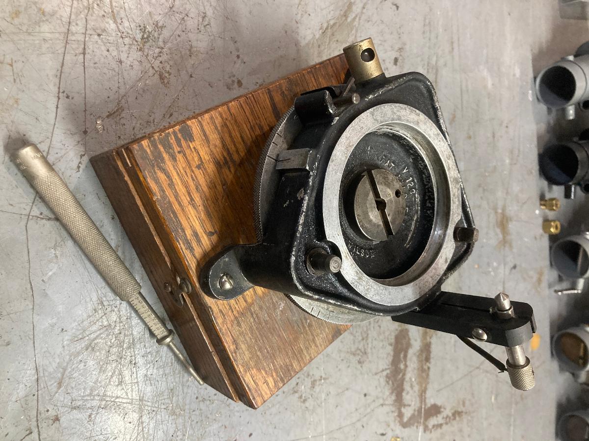