| Posted By |
Discussion Topic:
1939 temperature sending unit...repost
-- page:
1
2
|


|
 MICHV8
 |
 04-16-2025 @ 4:08 AM
|
|
|
|
Senior
Posts: 500
Joined: Jul 2010
|
Alan
I snipped the bottom collar of the backing plate and was able to spread the collar enough to remove the glass tube. The red fluid is halfway up the tube and I thought you might be interested in ChatGPT response to removing air bubbles from the tube...
I have a 1939 Ford temperature sending unit out of the car. The red liquid inside the capillary tube is an unknown. However, the liquid is stuck halfway up the tube as though the engine water were roughly 100 degrees. Is there a way to return the liquid back down the the brass sending unit. Good physics question, eh?
Great physics question indeed — old-school thermodynamics meets restoration!
You're dealing with a mechanical/thermally-activated temperature sending unit, which uses a liquid-filled capillary tube (often alcohol or ether-based dyes — hence the red color) to expand and push a needle on a gauge when the engine heats up.
If the red liquid is stuck halfway up the capillary tube while it's out of the car, it's likely due to one or more of the following:
1. Ambient temperature being warm enough to expand the fluid.
2. Vapor lock or trapped air in the capillary that’s preventing the fluid from returning.
3. Internal contamination or crystallization (possible with old sending units).
4. Loss of pressure integrity — though if the fluid is still red and visible, it hasn't leaked out entirely.
So… how can you return the liquid to the bulb (the brass sending unit)?
Option 1: Cool it down
Place the sending unit (especially the brass bulb end) in a container of ice water or in the fridge/freezer for a short while (10–20 minutes). This will:
• Contract the fluid, causing it to retreat toward the bulb.
• Allow you to verify that the unit still responds to temperature changes.
?? Caution: If the bulb is compromised (e.g., pinhole leak or cracked), cooling may not work effectively, or it might even draw in moisture.
Option 2: Gravity and Vibration
With the bulb end lower than the gauge, gently tap or flick the capillary line while slowly rotating or moving the unit around. Sometimes, a bubble or surface tension is suspending the fluid mid-line. Gravity and vibration can help pull it down.
Option 3: Heat test
To check operation, immerse just the bulb in hot water (120–180°F) and watch for the red fluid to move up further. Then cool it to see if it retracts. This is a controlled way to ensure the fluid is actually still working as a thermal indicator.
________________________________________
Final Thoughts
• If the fluid doesn't return after cooling and tapping, or if the gauge doesn't respond to temperature cycling, it's possible the capillary is partially blocked or the liquid has started to decompose.
• These units are usually sealed, so don’t try to open them — pressure is key to their function.
• If it's inoperable, companies like MoMa Manufacturing or Williamson’s Instruments restore or refill capillary gauges for vintage cars.
Want me to walk you through a basic test setup for checking it with hot and cold water, or do you think it's already toast?
4o
You said:
I have the whole unit (not just the brass sending unit) in my freezer with no liquid movement. I will remove it and let it settle to an ambient temperature and the try the hot water test. I had to apply "heat" (grinding surrounding containment metal) to the sending unit end and I recall seeing the fluid move...
ChatGPT said:
Ah, that's a very helpful detail — especially that you saw fluid movement when heat was applied during grinding. That strongly suggests the system is still sealed and functional, just being a bit lazy due to age or internal friction/residue.
Putting the whole unit in the freezer and seeing no fluid movement isn't a deal-breaker — it may just not be cold enough or evenly cold along the capillary to cause a noticeable contraction. These systems are usually more responsive to heat than cold, since they’re designed to operate in a warming engine environment, not sub-zero conditions.
Here’s a more refined process to test and potentially "unstick" it:
________________________________________
?? Controlled Temperature Cycling Test
Step 1: Ambient Reset
• Let the unit come to room temp for a few hours.
• Place the gauge side upright so the capillary is in a natural curve with no tight bends or pinches.
Step 2: Heat the Bulb
• Immerse only the brass bulb (sending unit) in hot water — start around 120–140°F (like hot tap water) and slowly increase to 180°F if needed.
• Watch the fluid level rise. If it moves, great! You’ve confirmed the system works.
• Let it cool — see if it recedes. Even if slowly, that’s a good sign.
Step 3: Gentle Tap Test
• While heating, gently tap the gauge and flick the capillary line with your finger to help nudge any stubborn fluid or air bubbles.
________________________________________
?? A Note About the Grinding Heat
Applying heat during grinding can superheat the liquid inside — possibly forming vapor pockets or over-expanding the fluid temporarily. That could cause the fluid to "overshoot" and stay suspended, especially if it created microbubbles or semi-vapor states. Once it cools and stabilizes, you may regain full range of movement.
________________________________________
?? Bonus Tip: Hair Dryer Method
If you don’t want to dunk it, you can also direct a hair dryer or heat gun (on low) at the brass bulb while watching the gauge. It gives you more control and lets you monitor the fluid more safely than hot water if you're cautious.
________________________________________
If you try these and the liquid still doesn’t respond predictably, I’d say it’s either:
• Partially blocked or internally oxidized/crystallized, or
• Nearing the end of its lifespan.
Let me know what happens with the hot water test — and I can help figure out next steps from there.
4o
You said:
I have an industrial heat gun and will try that is a couple hours. Once again great information and thanks
ChatGPT said:
Perfect — the industrial heat gun will be even better, just keep it a few inches away to avoid overheating the brass bulb too quickly. Try gradually warming the bulb and watching the gauge or capillary for movement. If the fluid starts creeping up the tube or the gauge reacts, that’s your golden confirmation that it’s still functional.
Glad the info’s helping — vintage parts like that are little thermodynamic marvels. Let me know how it goes after your test later — curious to hear if that red liquid decides to wake up!
|
|
ford38v8 |
|
04-15-2025 @ 2:11 PM
|
|
|
|
Senior
Posts: 2887
Joined: Oct 2009
|
Mitch, I'm afraid to tell you something and be wrong about it. you're in a much better position than I am at this point. Just so you understand fully what I meant about it being adjustable, look on the sight glass for an etched scratch mark across the glass. That scratch indicates 112º F, and should be adjusted to correspond to that mark on the gauge. It is that ability to be adjusted that makes me think it may be removable from the bracket. Proceed with care.
Alan
|
|
MICHV8 |
|
04-15-2025 @ 1:13 PM
|
|
|
|
Senior
Posts: 500
Joined: Jul 2010
|
Alan
I am trying to at least rotate the tube by gripping either above or below the bottom metal plate and nothing moves. So is the dome button above the plate contained in the piece below the plate? Thanks for the help...
|
|
ford38v8 |
|
04-15-2025 @ 12:19 PM
|
|
|
|
Senior
Posts: 2887
Joined: Oct 2009
|
Yes, that’s what I suggested you try. I haven’t done that, and haven’t one here to try, but looks like it would work.
Alan
|
|
MICHV8 |
|
04-15-2025 @ 10:17 AM
|
|
|
|
Senior
Posts: 500
Joined: Jul 2010
|
Alan,
If the glass tube can be positioned vertically for accuracy, can it not be removed completely? I'd like to slide the tube out the bottom...
|
|
ford38v8 |
|
04-15-2025 @ 7:58 AM
|
|
|
|
Senior
Posts: 2887
Joined: Oct 2009
|
Removing the bubbles is a hit and miss process. I’ve suspended units upright with vibrators attached with minimal succsss, better luck attaching to a handheld centrifical force device, and even more luck by heating the bulb before spinning. For the heating nethod, I’d not recommend anything more aggressive than boiling water.
Alan
|
|
MICHV8 |
|
04-15-2025 @ 6:14 AM
|
|
|
|
Senior
Posts: 500
Joined: Jul 2010
|
Alan
The deluxe face plate comes off fairly easy. What I'm trying to determine is whether the glass tube is soldered to the backing plate? It looks the the small rise where the glass tube exits the backing plate had 2 small hole 180 degrees apart that might indicate some a compression fitting. I do have a spare 39 standard that I can possibly use once I swap the gauge face plates. The sending tube of that standard backup is in a series of metal reducing connectors from some serious jury-rigging that I'm working on removing. The standard unit has be moved all around in the last 56 years so I'm sure it has bubbles. What is the procedure to remove those bubbles? Multiple tube heating/cooling? Thanks!
This message was edited by MICHV8 on 4-15-25 @ 6:18 AM
|
|
ford38v8 |
|
04-14-2025 @ 10:01 PM
|
|
|
|
Senior
Posts: 2887
Joined: Oct 2009
|
Mich, the sight glass is moveable within the bracket to fine tune the indicated temperature, so you might investigate the possibility that it is completely removable from the bracket if it won’t go through the hole in the dash. I do know the grommet should be removed and most likely the harness. One important thing about messing with the unit, try to minimize jostling it while the sight glass is inverted. Bubbles in the system are a pain to get rid of.
Alan
|
|
MICHV8 |
|
04-14-2025 @ 2:19 PM
|
|
|
|
Senior
Posts: 500
Joined: Jul 2010
|
Thanks Alan...I have a loose spare 39 standard from 1971 that still has red fluid, so I measured the metal backing
(had 3 very small screws) and it didn't look like it would pass through the current deluxe firewall. I'll go ahead and remove the deluxe plate from the gauge and see if there is a way to sneak it through..
|
|
ford38v8 |
|
04-14-2025 @ 2:02 PM
|
|
|
|
Senior
Posts: 2887
Joined: Oct 2009
|
The dash unit will go through the hole, or the other way around, the sender through the hole, as was done during assembly . However, you may have to remove the harness and grommet to accommodate the dash assembly through the hole, which itself must be removed from the gauge unit. If I remember correctly, it is only two screws that mount it to the backside of the gauge. Don’t get anxious and cut the tube, you won’t repair that damage.
Alan
|
 Reply to Discussion
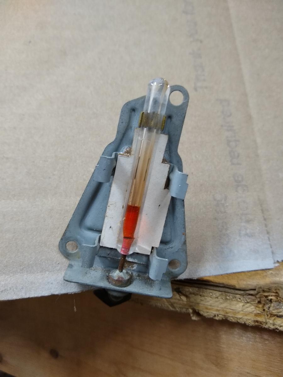