LOGIN
  • Post to the EFV-8 Forum
  • Post Classified Ads
  • Shop the Online Store
User Login

Not Registered Yet? Click Here to Sign Up!


(Forgot your Password?)
Remember me on this computer

Not registered yet?
REGISTER NOW!

Back to Home Page Show Forum Rules

Early Ford V-8 Club Forum

FORUM RULES: Users agree to these Rules when using Forum.

The site administrator reserves the right to change the terms and conditions of the user agreement without prior notice to the user. It is the responsibility of the user to regularly review the terms of this agreement.

The user agrees to the following terms:

  1. All information that you provide to us for your membership is correct.
  2. You will not use your membership to spam, harrass, or exploit other members in any way.
  3. Vulgar, Abusive, Racist and Sexist Language will not be tolerated.
  4. Commercial-type sales postings will not be allowed.
  5. No mass posting or flooding of the boards is allowed.
  6. No Advertising of parts or cars; no Ebay or business/commercial ads (please use the "Classified" for ads Wanted or For Sale).
  7. VIEWING MULTIPLE TOPICS ON SCREEN: You can choose to see more than 10 Topics at a time ... Log In and choose "Preferences" from the top bar on the Forum page. Scroll down and Change the "Default Topics Returned" parameter to 25 or 50, and save the changes. Since this setting is stored in your browser 'cookies' (if enabled), it seems to use that stored value even if you are not logged in. So, if you use a PC that you haven't logged into the forum from, the setting still seem to remain at the default.
  8. EXTERNAL PHOTO LINKS ON FORUM: You can still use external photo links in your posts on the new forum. They follow the rules of any link in that they have to have the URL link qualified down to the full image file name (example: .jpg). The links will open in a new browser window, the same as an uploaded image attached to a post. Since an image attachment to any post does not display inline with the post, the results are the same. You can use multiple external links within a post. This link is from photos on a site from Don Clink's 'Deuce@75' albums:

    http://donclink.com/deuce_75_1/images/dscn2950.jpg

    Using links from photo sites such as Photobucket can help in "size" issue with uploaded attachment files. For best viewing in web browsers, photos should be around the 800x600 pixel range, and probably not more than 1024x768. Most cameras today store HUGE jpg image files, as the default settings are in the 7, 8, 10, and 12Mb image sizes. The image files that are then attached are very large, and the browser can't display the full image size without using the scroll bars. Use the re-sizing functions of your photo editing software to reduce the image to 800x600, which reduces the file sixe and the image load time in the browser. Don uses Google's free Picassa3 software, which is an excellent photo management product. All of the photo albums of the Deuce, Grand National, and Auburn that are links on the NORG site were built using Picassa's web creation functions. And it's free? (THANKS to Don Clink for the info!)
  9. HOW DO I SHOW MY EMAIL ADDRESS ALONG WITH MY USERNAME? You can LogIn on the Forum, and select PREFERENCES. On this page Members can add optional information such as their City,State, Country; Occupation; Hobbies: list a Homepage; list AOL Instant Messanger Handle; Signature; "Make Email Address viewable to others;" and even change the number of Default Topics shown on a page. WHEN others click on your profile, they will see this information.

EFV-8 Club Forum / 1940 Ford Discussion / Heater Motor Questions

   Reply to this DiscussionReply to Discussion | Start new discussionNew Discussion << previous || next >> 
Posted By Discussion Topic: Heater Motor Questions

Printer-friendly Version  send this discussion to a friend  new posts last

pech33
06-06-2021 @ 3:45 PM
Member
Posts: 84
Joined: Mar 2011
          
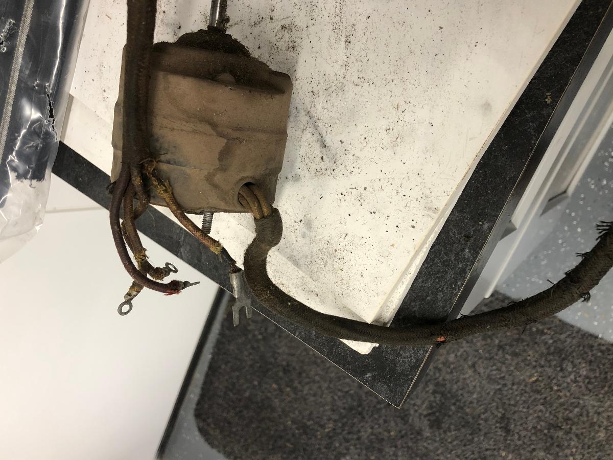
It appears that the heater motor is toast, I can't get it to budge. It spins by hand, but not on it's own. My question is this: single speed motors are offered online , my motor has four wires, I assume one power and three speeds. The switch has OFF and three clicks to the right, so I assume three different speeds. Am I correct? Any idea on who could rebuild this puppy? It is highly possible that I didn't give it a correct "hook-up" to test it. I grounded it to the block and hit the power wire to the negative terminal on the batter and then to the positive terminal after it didn't budge. No sparks, no nothing.


Also, now that the heater is down, is there a problem if I connect the heater hoses together and let it recirculate through them until I get the new heater motor?

Thanks in advance.

carcrazy
06-06-2021 @ 9:19 PM
Senior
Posts: 1587
Joined: Oct 2009
          
There is no problem with you hooking up the two hoses to each other allowing engine coolant to just circulate through them. The only 6V heater motor that I found is offered by MAC's Auto Parts. It is a single speed unit and not listed as fitting a 1940 Ford. It claims to be a universal motor that will work on 1941 and later Fords. This unit could possibly be made to work with minor modifications.

You might be able to get your current motor repaired in your area. Look for an electrical repair shop that does starters and other motors.

TomO
06-07-2021 @ 7:44 AM
Senior
Posts: 7243
Joined: Oct 2009
          
You did not test your motor accurately. All 4 wires must be connected to either a ground or a voltage source. It sounds like you do not have a correct switch for your heater motor. The correct switch has OFF in the center position and HI and LOW Indirect flow when turned to the right. Turning the switch to the left should give HI and LOW Direct heater flow.

There are 4 wires coming from the motor. The yellow and the green wires come from the field windings and the red and brown wires come from the brushes. If your colors have faded so they all look yellow, I use an ohm meter to make an initial guess as to which wires are from the brushes and which wires are from the field and then I use a battery hooked up to a switch to determine which of the wires used for forward and reverse direction of the motor.

Usually you can see a little of the green cast on the green wire and the red color on the red wire. If you connect your ohm meter between the green wire and the yellow wire, you will have near zero ohms resistance. Any other wire will show an open condition. The reading will not vary when you rotate the motor shaft. When you connect the red and brown wires, you will have more resistance than the field connections showed and it will vary slightly as you turn the motor.

Three of the wires from the motor will be attached to the switch according to the colored dots next to the terminals on the switch, the green wire will be attached to ground and the terminal with the black dot will be attached to a 6 volt source. The red and brown wires control the direction of the motor. When the switch is in the HI Direct position the fan should be blowing air through the heater core. On 1940 heaters this means that the motor is turning counter clockwise

Your green wire has a spade connector, so you are halfway home in identifying the wires.

The most common cause of the motor not running is because the brushes are worn. If you take your motor to a shop for repair, buy a new wiring harness and have them install it for you. I would opt for the repair option rather than install an aftermarket motor that will not fit inside the heater correctly.

Let us know how you made out.

Tom

pech33
06-07-2021 @ 9:26 AM
Member
Posts: 84
Joined: Mar 2011
          
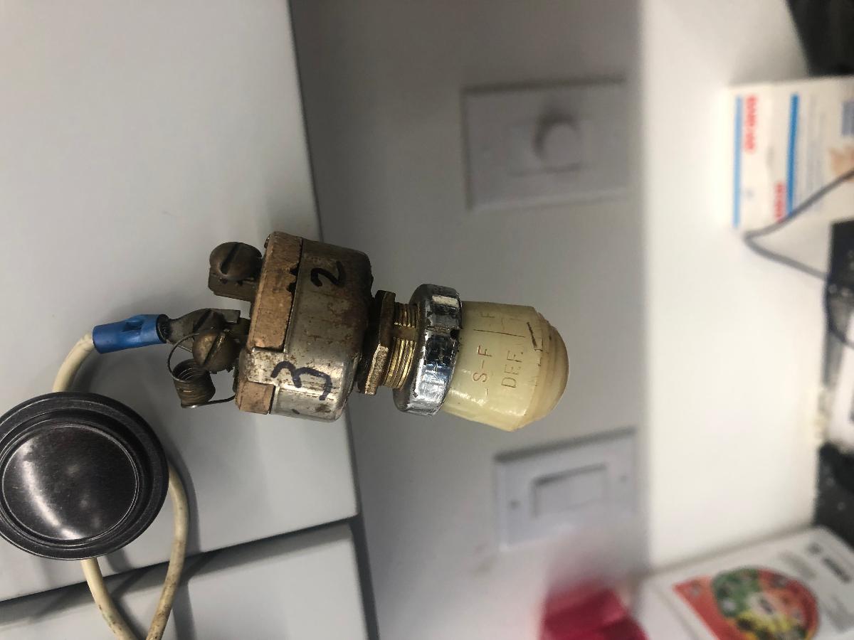
Here is the switch, it says: S-F with DEF. underneath it and on the right side is says F-S with HEAT below it. I will attempt to pull off your test. Thanks.

pech33
06-07-2021 @ 9:33 AM
Member
Posts: 84
Joined: Mar 2011
          
OK, I think I understand the switch. Off is in the center, left has S for slow F for fast for the defroster. Right has F for Fast and S for slow. F is the first "click going left or right with S being the second option.

40 Coupe
06-07-2021 @ 2:36 PM
Senior
Posts: 1647
Joined: Oct 2009
          
The switch is from a hot water heater and appears correct in appearance and the operating knob is correct. Two of the wires in the motor are the field, two wires are the armature. Can you use an Ohmmeter?
The wire with the split spade connector is ground it goes to one lead of the field windings and is green. To find the other field wire use your ohmmeter on the the green wire and check the other three wires for continuity that wire should is the second field wire and is yellow.
The remaining two wires are the motor armature. If you connect the ohmmeter across them you should also find continuity. one wire is red and the second is brown.
Connect the brown wire and yellow wire together then connect battery - (Negative) to the red wire and battery + to the ground wire with the split spade. The motor should run, or try to, if so it is good.
You can buy another wiring harness for the motor from several of the wiring suppliers.


This message was edited by 40 Coupe on 6-7-21 @ 2:52 PM

40 Coupe
06-08-2021 @ 5:05 AM
Senior
Posts: 1647
Joined: Oct 2009
          
Wiring diagram to the switch below

This message was edited by 40 Coupe on 6-8-21 @ 5:17 AM

pech33
06-08-2021 @ 7:19 AM
Member
Posts: 84
Joined: Mar 2011
          
Thanks . Excellent. I have a new harness on the way and I have two local sources that can rebuild the blower motor. It is amazing to take the heater apart and I marveled at the engineering of the day (1938+) in how they designed the parts and pieces to all fit together in a relative small package to heat the cabin. It reminds me of going through a WWII airplane and looking at the simplicity of the systems and the ingenuity of the designers. I have had this car about two months and I am fascinated with it. The vacuum system on the top is on the agenda. It tries to lift, but I think the canisters need attention. Once again, simple but ingenious. I should have bought one of these 30 years ago instead of my bubbletop.

Pat’s 40 Ragtop

This message was edited by pech33 on 6-8-21 @ 7:24 AM

pech33
07-19-2021 @ 12:25 PM
Member
Posts: 84
Joined: Mar 2011
          
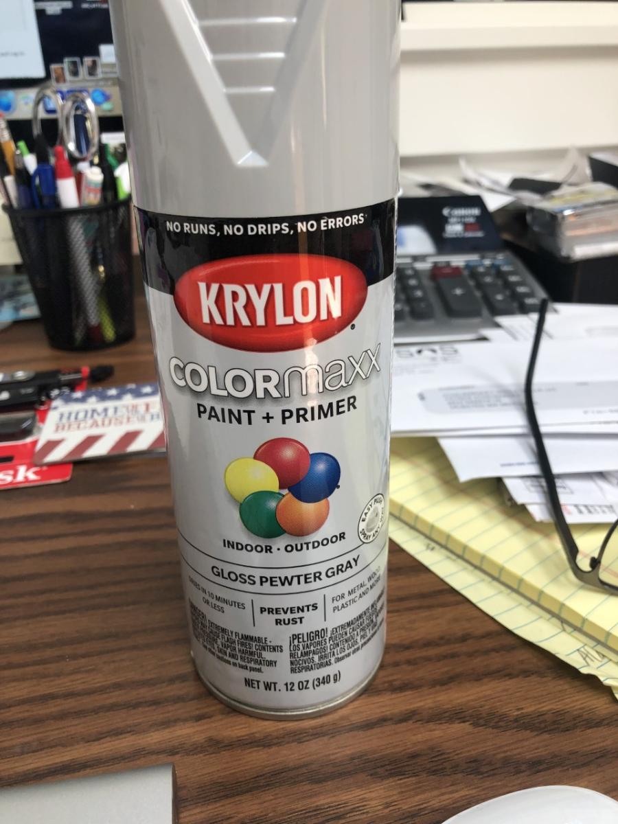
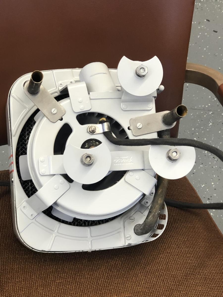
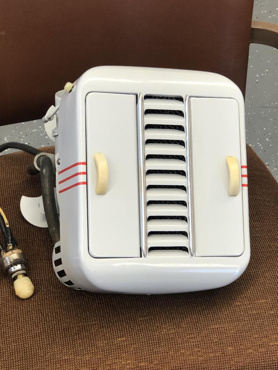
Just finished the heater. Found the paint at Lowes, Gloss Pewter Gray. Instead of trying to paint the three red stripes on each side, found pin striping tape, 1/8" at O'Reilly's for $2.00. It is not being judged so I don't care if it is absolutley correct. The switch still has an issue. It works on Defroster F & S (fast and slow I guess) and the Heater only works on F. I assume the switch needs to be taken apart and looked at. I doubt I will be using the heater with the top down. If it's raining, I'm not driving it.

Pat’s 40 Ragtop

<< previous || next >> 


NOTE: YOU MUST BE A REGISTERED USER AND BE LOGGED IN TO POST (and reply to) messages in this forum. If you are a first time user, please click the CREATE A NEW ACCOUNT in the masthead above to register and Log In. After that, all you do is LOG IN to enjoy using this site.

DISCLAIMER: The V-8 Club does no independent testing of any of the opinions, thoughts or suggestions presented in the website on the Forum, in the Tech Tips section, or any section. A reader should consider the website to be a forum wherein differing solutions to a particular set of circumstances may be discussed. Ultimately, the selection of an item for an individual's vehicle must be based upon the independent study of the vehicle owner in consultation with people in the hobby and restoration experts.


EFV-8 Club Forum Home | Back to Home Page | Contact the Webmaster

Copyright © 2009 - EFV-8.org
Powered by < CF FORUM > v.2.1