| Posted By |
Discussion Topic:
oil filter
-- page:
1
2
3
|


|
 chrismac
 |
 11-26-2010 @ 5:20 AM
|
|
|
|
Member
Posts: 68
Joined: Dec 2009
|
In restoring my 1940 station wagon, I am installing an oil filter. The vehicle did not have one but I found a good used canister and mounted it on the left cylinder head. I didn't get any lines or fittings with the canister. Can someone tell me about the plumbing so I can connect the canister correctly? The 1940 Ford Book suggests both inlet and outlet lines were flexible, which I assume means black rubber.
Thanks!
Chris
|
 kubes40
 |
 11-26-2010 @ 6:52 AM
|
|
|
|
Senior
Posts: 3366
Joined: Oct 2009
|
Chris, Below is probably more than you'd ever wanted to know about oil filters. Hope it helps!
Mike "Kube" Kubarth
One design of filter assembly was offered for the 85 and 95 horsepower engines. Fit with part #01A-18658-A and supplied to Ford by the Fram Corporation of Rhode Island, these units were normally installed at the dealership.
The filter housing was vertically mounted to the left cylinder head above and between the #5 and #6 cylinders with three special #350710-S7 nuts.
This assembly utilized a replaceable filter element.
Both the housing body and cover were painted gloss black. The steel cover retaining bolt, 01A-18691 was plain finish. Beneath that bolt was a copper flat washer.
A red, yellow, black and gold decal was placed on the cover. It indicted the filter was manufactured exclusively for Ford by the Fram Corporation and utilized a replacement cartridge filter, #01A-18662.
Some unique features of a proper 1940 filter housing are depicted in the photo.
The inlet is on the right side, near the bottom of the housing and is fitted with a 90* brass fitting. Directly below that fitting is a decal that simply indicates “INLET”. On the very bottom and center of the filter housing is a threaded hole that was fitted with an identical 90* brass fitting as the inlet. This port is used to return the oil to the engine. Just to the front (left) of this fitting is yet another threaded hole. This drain hole was fitted with a brass hex head plug.
Made from an oil resisting compound and covered with a black lacquered braided cloth, both pressure and return hoses were supplied to Ford by the AC Spark Plug CO. All fittings were brass – swivel type. The only exception being the late return hose which had a “banjo” fitting on one end. The exterior of the hoses was rough - obvious evidence of the cloth covering.
While there were two different routings of the oil return hoses, there was but one routing for the pressure line.
The pressure hose threaded into a special angled brass reducing elbow fitting, 01A-18669 (photo #A) that was fitted to the horizontal threaded hole near the oil pressure sending unit. The hose was then routed near the bottom row of cylinder head studs and attached to the inlet fitting on the right side of the filter housing. A cadmium plated clamp (photo # B) which was placed beneath the cylinder head stud between and just below cylinders #7 and #8 held this hose in place. A 27081-S screw and 34141-S nut were utilized with this clamp. There were two designs of this particular clamp. One design had a slot, while the second had a hole.
The first routing of the oil return line ran between the fitting at the very bottom and center of the filter housing and a special bolt / fitting that replaced the bolt at the left fuel pump flange. This was the most common routing having been utilized from the beginning of 1940 production until the very end of
April, 1940.
This return hose was routed through a hole on the rear of the filter housing bracket. A rubber grommet was placed in this hole to insulate the hose against abrasion. Traveling backward along the top of the spark plug conduit, the hose was scr*w*d into a special fitting, 01A-18661 (photo #C) that had replaced the left fuel pump mounting bolt. A cadmium plated clamp (photo D) held this line to the left spark plug wire conduit. This clamp utilized a 26515-S2 screw and 34129-S2 nut.
At the very beginning of May, 1940, the return line routing was revised. The hose came from the bottom and center fitting of the filter housing and ran through the rubber grommet in the base but now was routed forward.
A special hollow bolt with two copper gaskets replaced the bottom – right distributor mounting bolt. The newly revised return hose (photo #F) had a “banjo” fitting on this end to accept this hollow bolt. To hold this line in place, a cadmium plated clamp was placed beneath the washers of the generator mounting stud.
A 27081-S screw and 34141-S nut were utilized with this clamp.
|
 chrismac
 |
 11-27-2010 @ 5:37 AM
|
|
|
|
Member
Posts: 68
Joined: Dec 2009
|
Thanks Mike. Whoever wrote this knew his stuff! Any idea where it came from? I'd sure like to see the pictures referenced. Dennis Carpenter does not make the flexible hoses for the filter. Do you anyone else who has reproduced them?
Chris
|
 kubes40
 |
 11-27-2010 @ 5:39 AM
|
|
|
|
Senior
Posts: 3366
Joined: Oct 2009
|
Hi Chris,
I wrote that, so - thanks for the kind words 
I can email pictures to you directly. Your email address again?
Mike
|
 chrismac
 |
 11-27-2010 @ 3:18 PM
|
|
|
|
Member
Posts: 68
Joined: Dec 2009
|
e mail me at cemac@macallister.com
Thanks!!!
|
 kubes40
 |
 11-28-2010 @ 6:05 AM
|
|
|
|
Senior
Posts: 3366
Joined: Oct 2009
|
Email is on it's way Chris...
|
 MikeJ
MikeJ |
 11-28-2010 @ 5:47 PM
|
|
|
|
Member
Posts: 9
Joined: Oct 2010
|
Attached is a photo of the lines & fittings as provided by Mike Kubarth. Thanks Kube!
|
 MikeJ
MikeJ |
 11-28-2010 @ 5:51 PM
|
|
|
|
Member
Posts: 9
Joined: Oct 2010
|
And a photo of the oil filter housing and original box, also provided by Kube. Thanks again!
|
 kubes40
 |
 11-28-2010 @ 6:03 PM
|
|
|
|
Senior
Posts: 3366
Joined: Oct 2009
|
Hey Mike,
How the heck do you post pictures on this site? Tell me, tell me, tell me. Pretty please ?
Mike "Kube" Kubarth
This message was edited by kubes40 on 11-28-10 @ 6:04 PM
|
 TomO
TomO |
 11-29-2010 @ 8:57 AM
|
|
|
|
Senior
Posts: 7243
Joined: Oct 2009
|
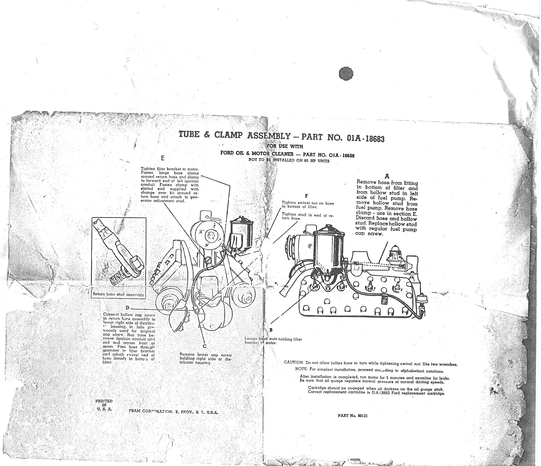
Here is a copy of the installation instructions for the hoses.
Kube, to upload photos, click on the "Choose File" box just below your reply on the 'Reply to Topic' page. Then open the folder on your computer that has the photo and click on the photo and open the file. The photo will then be uploaded. You will not see the photo until after you submit the reply.
Tom
|


 Reply to Discussion


 chrismac

